New cycle for switch cabinets
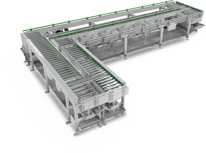
The conveying sequence or production process works as follows:
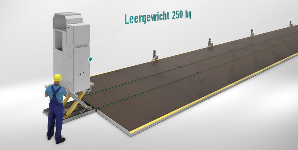
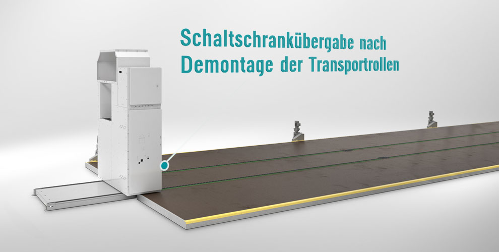
The empty control cabinet is moved on rollers over the lifting table, which is positioned at the beginning of the conveyor line. Afterwards the lift table lifts the switch cabinet vertically so that the employees can remove the rollers manually.
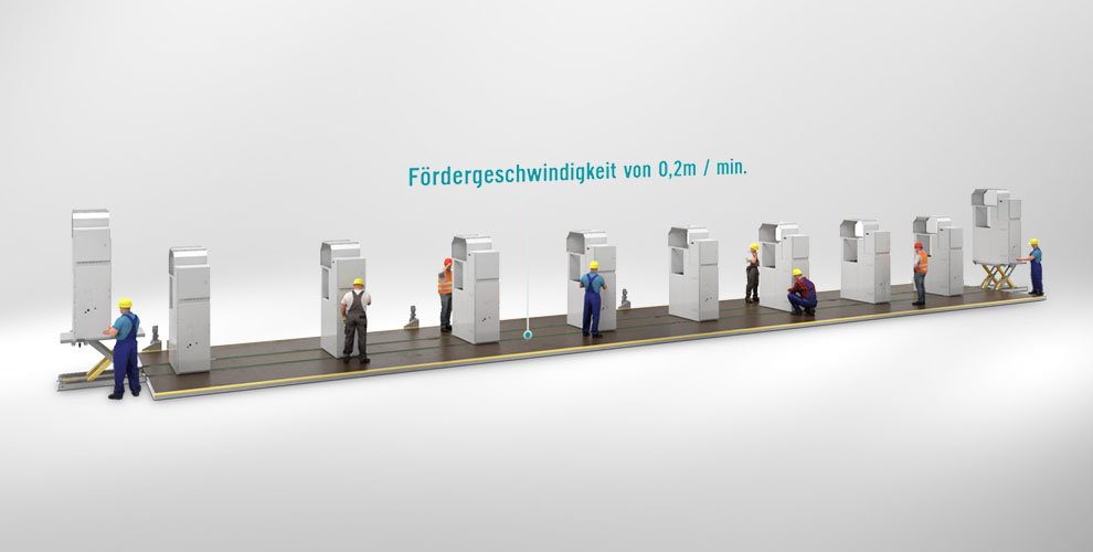
Then the lift table moves down again and transfers the control cabinet to the chain conveyor. This moves it onto the accessible assembly conveyor, which is equipped with a constant feed rate of 0.1 – 0.2 metres per minute. This results in a total assembly time of 2 – 4 hours per switch cabinet.
While the control cabinet is being transported on the assembly conveyor line, its walk-in environment provides direct access for employees to equip it with the required components and groups.
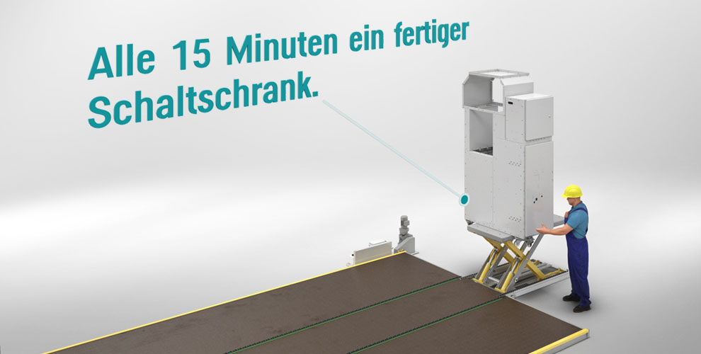
At the end of the assembly line, the lift table lifts the completely filled switch cabinet and the employees reattach the transport rollers.
The lifting table lowers the switch cabinet together with the rollers back down to the floor. From there, employees transport it to the desired storage location.
The customer benefits:
- The conveyor system enables the setup and control of cycle times and work processes.
- The overall productivity of the production becomes measurable.
- The manufacturing costs of the individual cabinets become standardized and more transparent, which allows a more precise price calculation from a commercial point of view.
- The transport routes between the individual work stations are eliminated.
- The physical strain on the employees is considerably reduced.
- The system can be easily extended.
- ALFOTEC organised the complete project logistics including transport, customs clearance, certification and additionally supervised the installation and commissioning on site.
Precise handling of workpiece carriers
The solution – the process
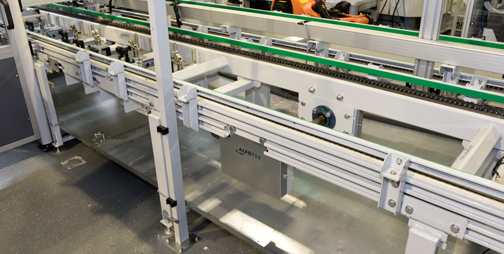
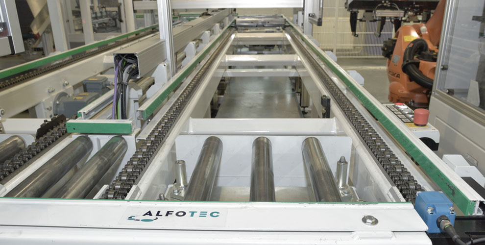
1. The loaded carrier plates are first buffered on an accumulation chain conveyor and then separated. From there they are transported by chain conveyor and roller conveyor to the individual work stations.
2. In order to collect the oil dripping off during the machining processes, oil sumps were installed along the entire conveyor line. These can be emptied manually via a drain connection as required.
3. Thanks to the specially developed frame construction, the production line can be expanded with additional lifting stations.
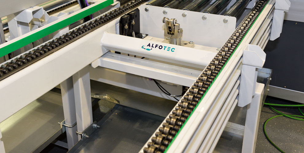
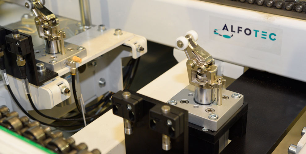
4. Each of the seven working or lifting stations is equipped with a vertical stopper system which ensures that the carrier plate remains in position for a defined time interval.
5. To enable a high throughput, several buffer zones were set up on the production line.
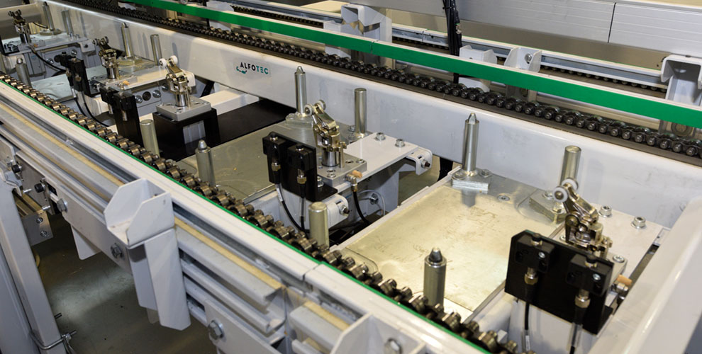
6. In order for the robots and machines placed at the work or lifting stations to operate precisely and without interference, the carrier plates must be lifted vertically. This initially posed a problem: The pneumatic lifting stations were originally equipped with four extended centering bolts. This resulted in the carrier plates becoming wedged during centering, so that precise machining of the workpieces was not guaranteed.
7. Since absolute precision is a mandatory requirement for avoiding rejects in fully automated work processes, another solution had to be developed. Two diagonally opposite centering bolts were left in their original design, while two support bolts were specially manufactured and installed for the other two centering bolts.
8. After processing at the lifting station, the vertical stopper system releases the material for further transport on the production line.
9. After the carrier plates have passed through the complete production line and machining centres, the workpieces placed on them are ready for further transport or processing at the take-off station and the carrier plates can be reloaded and components removed.
The customer benefits:
- Very high manufacturing quality
- High centering accuracy – no waste
- Trouble-free access to the workpieces
- Fast throughput times
- The conveyor line can be easily extended
Malaysia refreshed
The task and special challenges
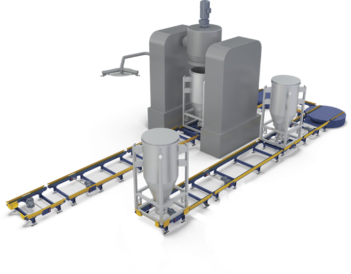
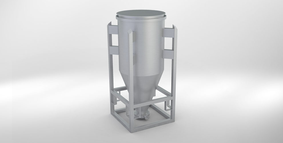
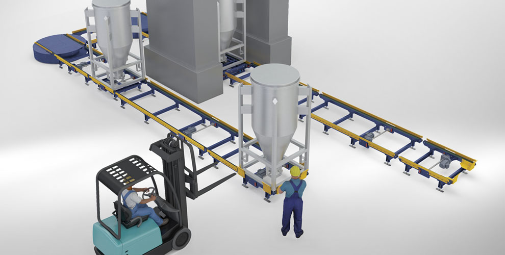
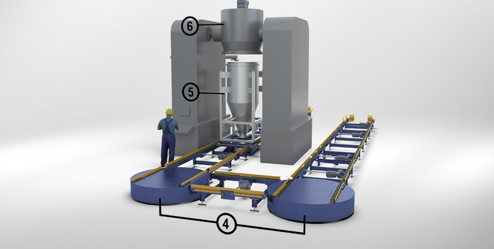
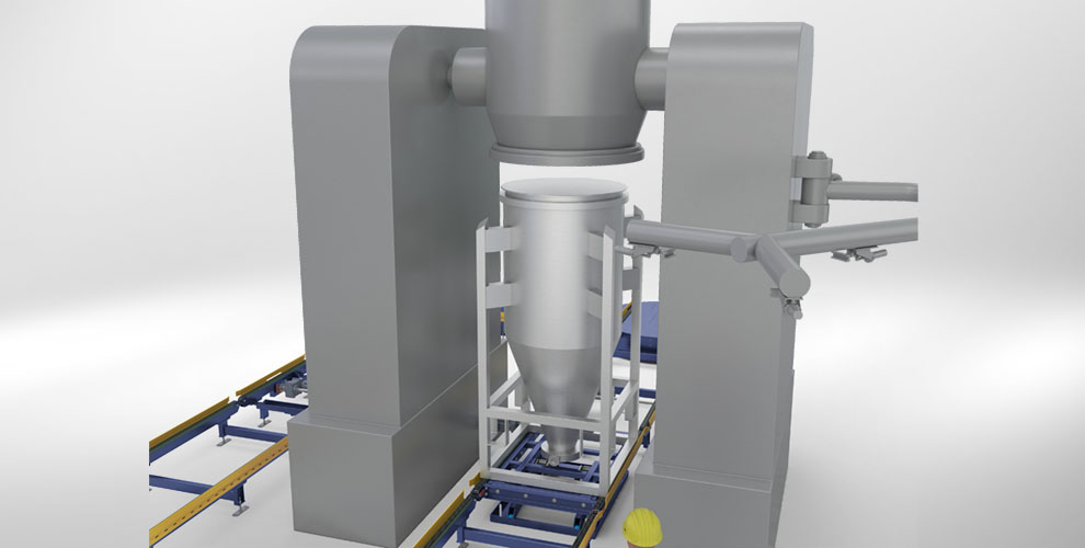
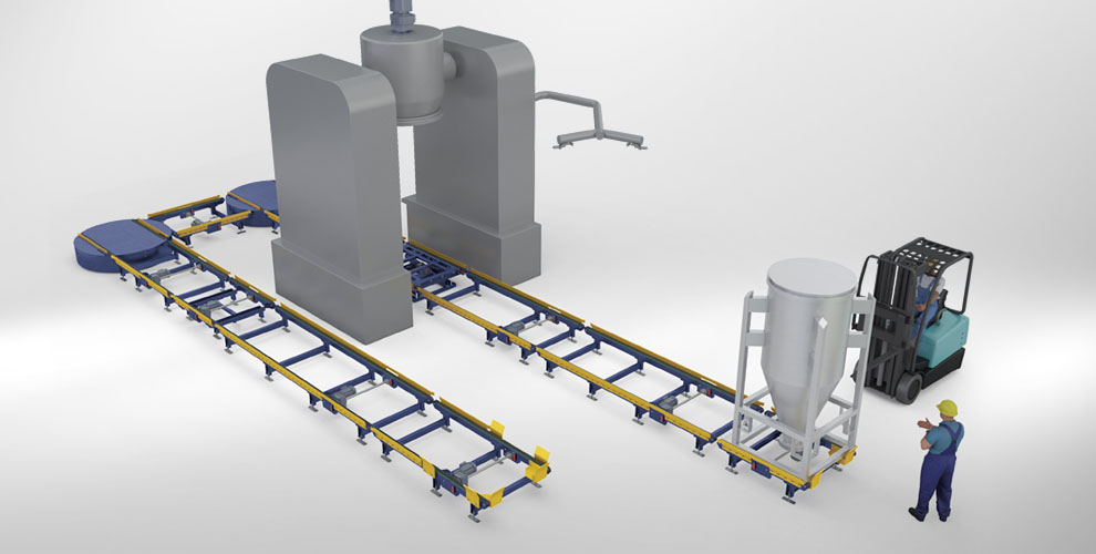
The task was to supplement an existing mixer station with a conveyor system to be developed by us in such a way that the mixing process and the transport of the material to be conveyed between the feed and take-off station could be fully automated in future – without the need for expensive conversions at the mixer station. Stainless steel containers with surrounding frames are used for the material to be conveyed. These are filled with various, precisely defined components, which are mixed by rotation in the mixing station. The containers, including frames, have the external dimensions 1,200 x 1,200 x 2500 mm (W x L x H) and can weigh up to 1,500 kg.
Furthermore, a weighing device should be integrated into the conveyor system in order to determine the total weight of the respective container contents. The main problem was that due to the required low overall height at the mixer station, our lifting tables were too high even in the lower end position. So we had to come up with an innovative idea to solve this problem – a challenge that we met with enthusiasm and high motivation.
The idea:
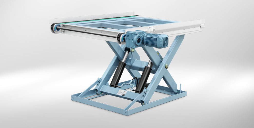
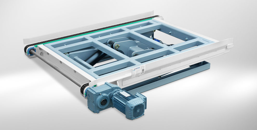
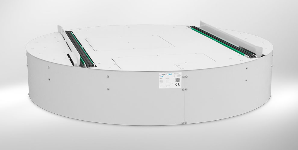
In order to reduce the height of the lifting table in the retracted state to the construction dimension required at the mixer station, we developed a lifting table with a circulating chain conveyor instead of a surface-mounted chain conveyor. This chain conveyor moves to different heights at the mixing station, so that the individual steps of the mixing process can be carried out fully automatically.
The entire conveyor system
The conveying process:
The driverless transport system available in the company transports the container to the feeding station of the U-shaped conveyor system. This is identical in construction with the take-off station at the end of the conveyor system.
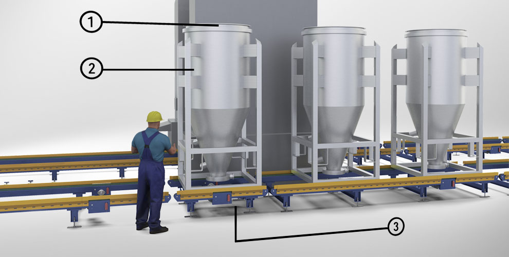
From the feeding station the container (2) closed with a lid (1) is transported to a chain conveyor with load cells or to the weighing station (3). There the exact weight of the container contents is determined.
The container (5) reaches the mixing station below the mixing drum (6) via two revolving platforms (4), each of which rotates 90 degrees.
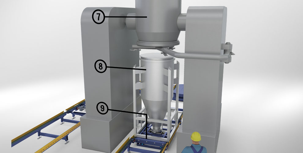
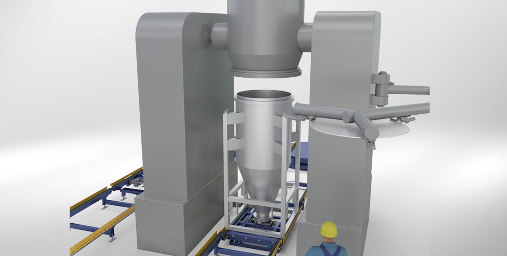
So that the lid arm can swing in between the drum (7) and the container (8), the newly developed lifting table (9) with circulating chain conveyor lowers into the lower end position.
The chain conveyor now moves up to the removal level of the lid gripper so that it can grip the lid.
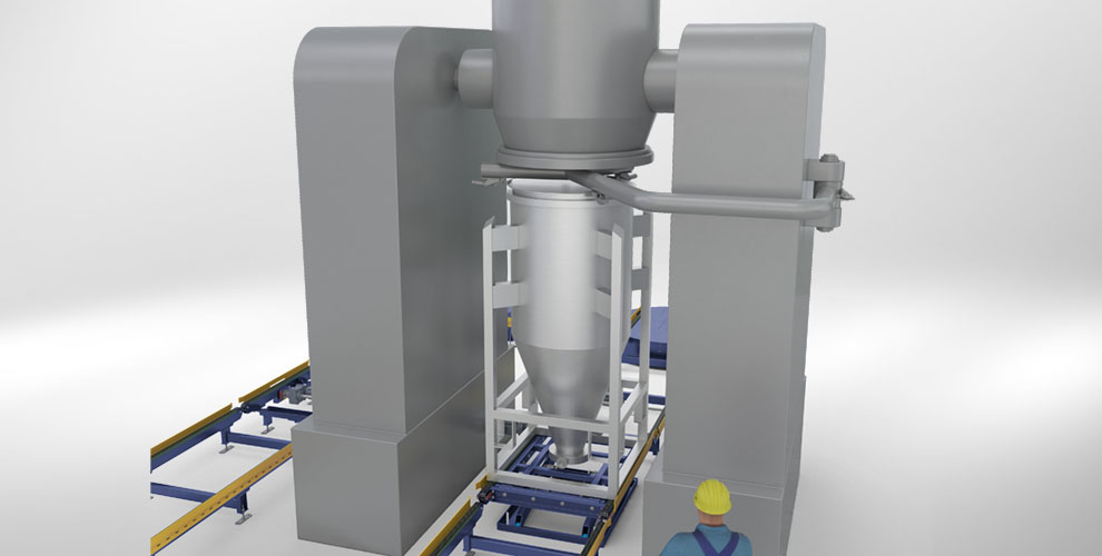
The lifting table with the container lowers to the lower end position.
The lid arm swings away with the lid.
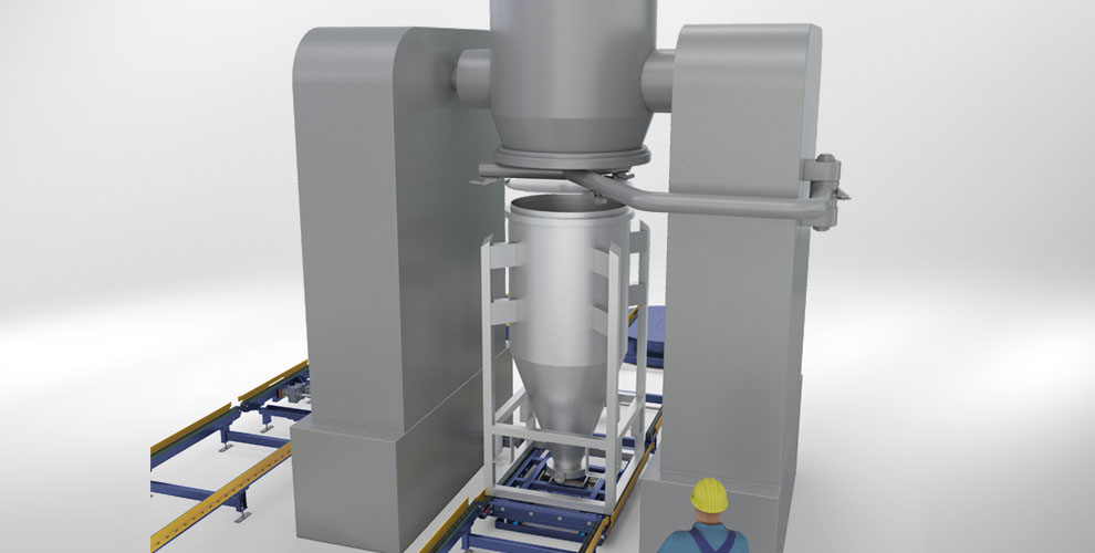
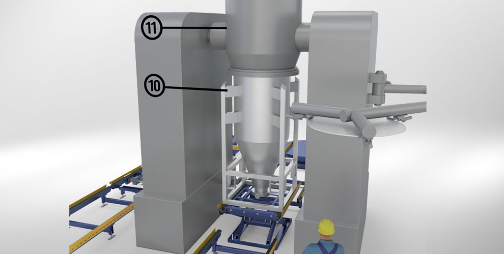
The chain conveyor now moves up completely until the container (10) docks with the mixing drum (11) and locks the container.
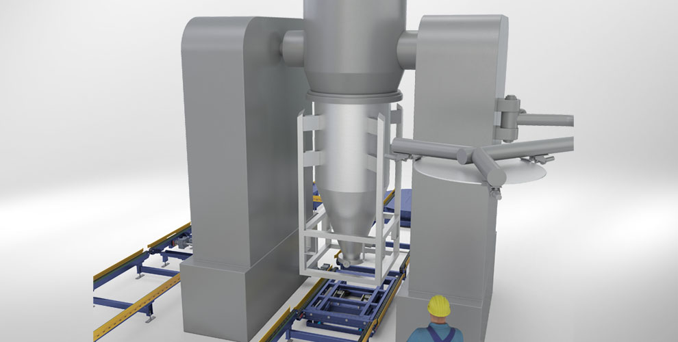
The chain conveyor then moves down completely so that the container hangs freely suspended on the mixer drum.
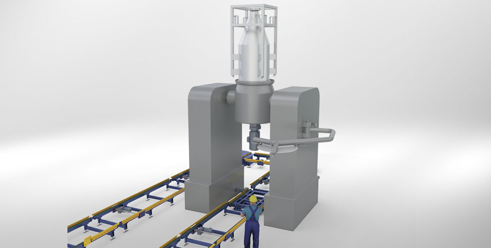
Now the actual mixing process takes place: It consists of a slow 180 degree rotation so that the contents get into the mixing drum and are then mixed by a screw (like in a concrete mixer). The container then turns back again by 180 degrees.
After the end of the mixing process, each container is placed back on the lifting table with circulating chain conveyor after steps 4. to 8., which then take place in reverse order.
From there the containers are automatically transported to the delivery station where they can be picked up by the driverless transport system for further use.
The customer benefits:
- 100% integration into existing operational intralogistics
- Trouble-free transport of the material to be conveyed
- Faster throughput times – higher productivity
- High operational safety – minimal risk of downtime
- The conveyor system is designed in a modular way so that it can be easily extended if necessary.
We had already developed a similar system on behalf of the managing director of our client in 2004, when he was still working for another company in Germany. This plant is still operating trouble-free today – and was probably the best recommendation for us as to why the company chose ALFOTEC when awarding the contract.
Integration into a test cell
The task:
Synchronisation of measuring and conveyor technology
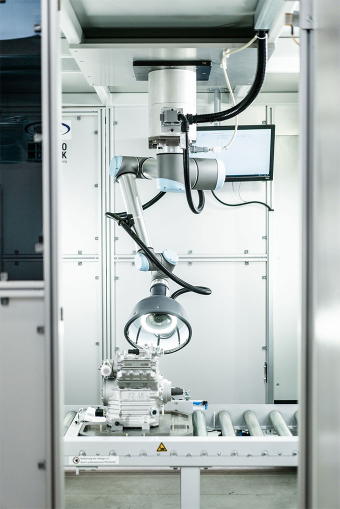
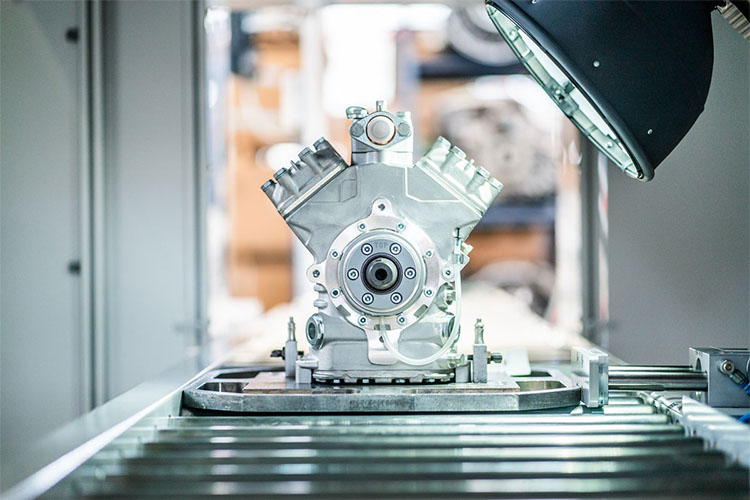
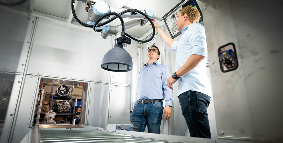
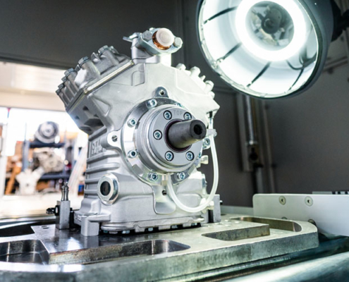
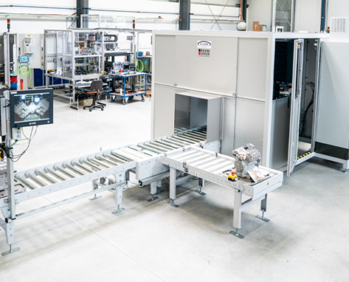
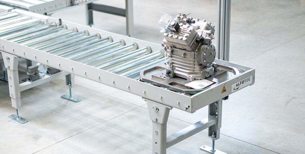
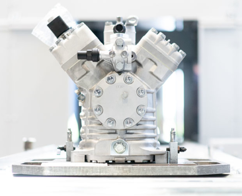
The challenge of the project was the synchronization of the measuring and conveying technology. The task was to check various compressors or compressors for transport refrigeration in the automotive industry in the planned plant for completeness of the installed components. Subsequently, the compressors were to be distributed according to the result in an area for correct and incorrect ones in order to divide them up for further transport or for reworking.
In the course of planning, the project was initially reduced to only one type. The task was still to design the plant in such a way that an extension of the system with additional types could be realized at short notice and without major modifications to the existing plant. The requirement for the conveyor system was not only the transport, but above all the exact positioning of the compressor mounted on a goods carrier in the area of the robot test arm. This runs along a precisely defined path to check all parameters and does not automatically align itself to the workpiece. In addition, the design of the conveyor system, especially in the area of the test cell, had to be adapted to it and aligned with the existing layout of NeuroCheck GmbH.
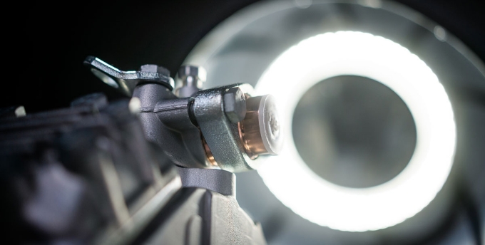
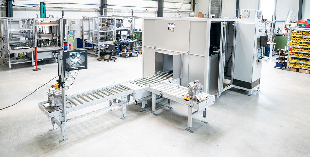
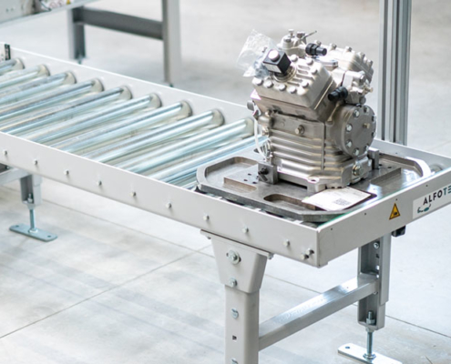
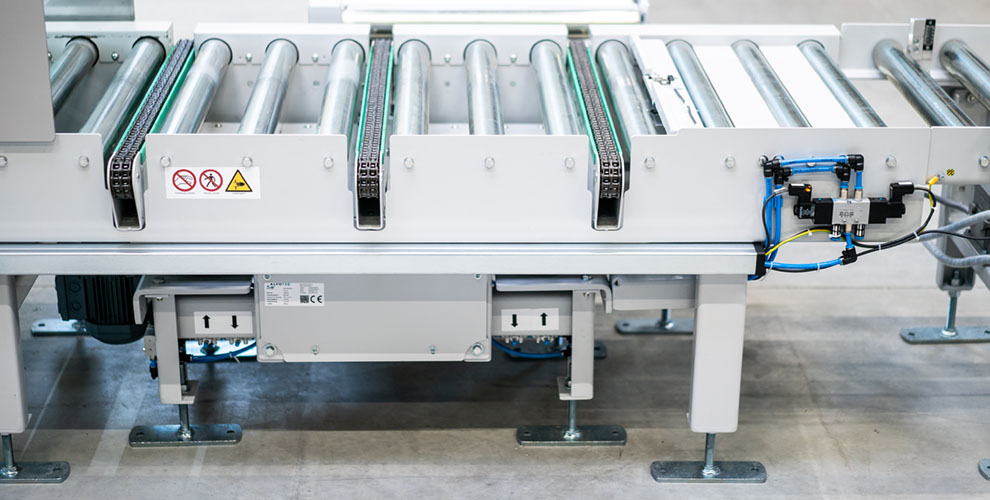
A modular construction approach with preparation for the next expansion stages, where additional elements can be added very quickly and easily, is the optimal solution here. In the first expansion stage, the carrier plate is still manually fed onto the upstream conveyor system, the QR code for the system’s inspection process is scanned and moved into the cell. There the workpiece carrier is aligned in longitudinal and transverse direction by a pneumatic system and checked for completeness of all components by the robot arm and other camera systems on the basis of 24 defined positions. After the inspection, the product carrier with compressor leaves the test cell and, if the test result is positive, is moved to a removal position for further processing by means of a chain ejector, or else transported to a corresponding place for reworking.
A control system is present at the post-processing position, which provides the worker with all the information that the inspection system has worked out. This enables him to make the necessary changes and subsequently confirm the workpiece as checked and OK. Various precautions have already been taken to expand the system. For example, the infeed section can be extended as required and can thus serve as a buffer section but also as a junction for introducing various other test objects. The system is already designed with a comfortable width and load capacity to be able to transport and test larger dimensioned product carriers. The chain ejector is also designed with an additional chain strand and a reversible drive for further transport of other types after the test cell.
The customer benefit
The individually planned conveyor system from ALFOTEC GmbH is an ideal complement to the robot test cell from NeuroCheck GmbH and enables the end customer of KLUMA GmbH to provide the finished compressors with a reliable seal of quality. The conveyor system offers:
- Precise transport and alignment of the workpiece carriers.
- Fixation of the compressor in the test position.
- Individual further transport according to the test result.
- Modular extension and exchangeable construction.
- A design already designed for future requirements.
Assembly line assembly of office desks
The solution: combinations of link belt, belt and roller conveyors with lifting table
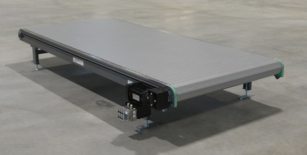
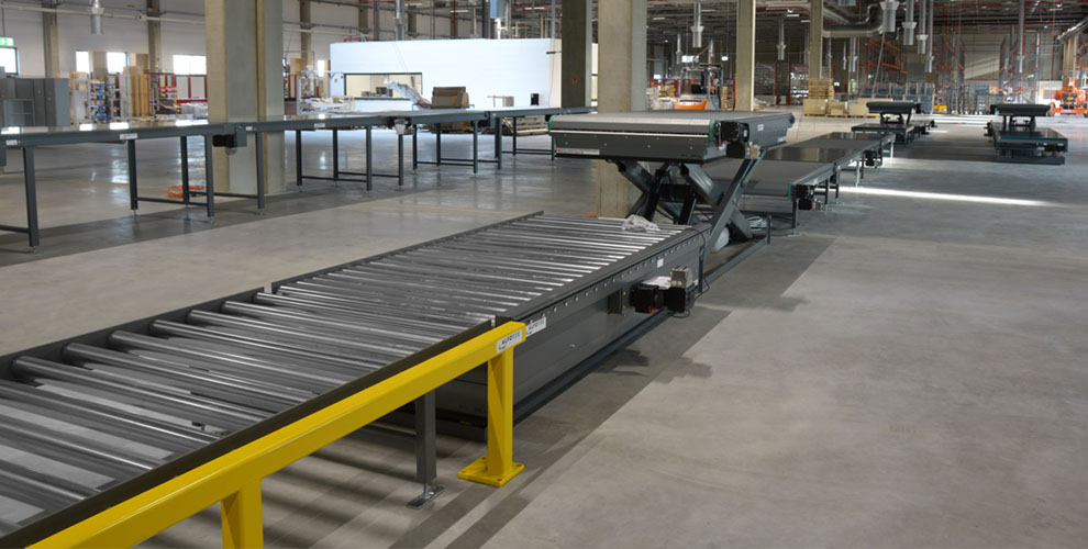
In order to ensure that the tables could be assembled on the assembly line by employees, a stable and full-surface system had to be chosen. Apron conveyors were the best solution, because they can take high loads not only over a large area but also at specific points for short periods. Thus, apron conveyors were provided at all workstations in the assembly series, such as mounting the base on the frame, laying the electrical cables, etc.
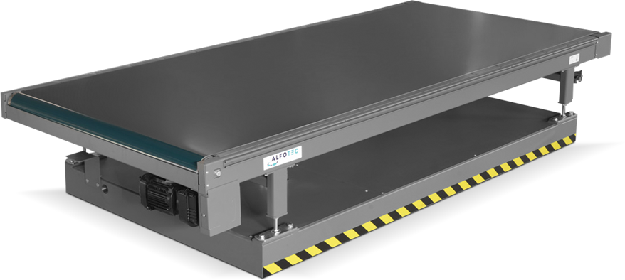
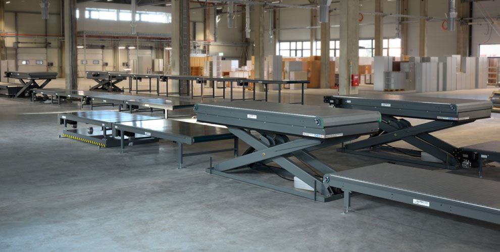
This system was also chosen for the functional test following the electrical installation, but it was supplemented by one of a total of five lifting tables. On the one hand, this serves to ensure ergonomic work for the fitters, but on the other hand it is also intended to lift the table to the next working height. If the conveyor system is still at a lower working height of 400 mm up to this point, the tables will have to be mounted at a higher level of 600 mm in the next steps, which is why the lifting table will move to this level.
Since two assembly lines run identically next to each other up to the section of the function test, but the subsequent sections are only planned as simple for the time being, a transport from the left to the right section had to take place. This was implemented by means of a traversing carriage that travels back and forth between the two sections and transports the tables from the pre-assembly line to the subsequent work steps.
After each assembly station there should also be a buffer space for intermediate storage of the tables, which is why somewhat lighter belt conveyors were used here.
At the end of the assembly line the finished tables were to be packed and wrapped for further transport, which was done by a machine provided by a supplier. For this purpose, it was necessary that the conveyor at the packaging station could be adjusted in height, which is why a lifting table with an apron conveyor was again the optimal conveying element.
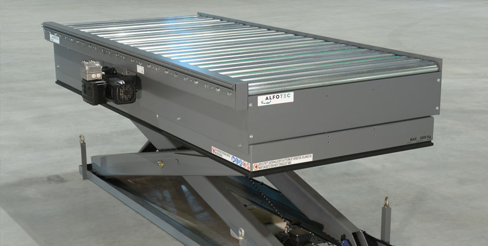
In the last step the ready assembled and packed table should be prepared for stacking. For this purpose, the table had to be lifted by means of a lifter integrated in a roller conveyor to enable the employee to lift the table by means of a gripper and thus stack it on the downstream roller conveyor. However, since these stacks will be up to three tables high, the lifting roller conveyor itself had to be adjustable in height, which is why it was also reinstalled on a lifting table that can move to three predefined positions, thus enabling easier transfer.
The production line of the standard tables was identical in construction, only that the work steps of frame and electrical assembly could be omitted, making it much shorter.
Manual order picking and conveyor technology
The challenge
Delivery of an individual conveyor system for picking pallets in cardboard boxes. The new roller conveyor system is to be replaced during operation.
The existing conveyor technology had already reached its maximum service life after five years of operation due to the high level of use. This presented the perfect opportunity to optimize processes and improve ergonomics! In addition, the new conveyor lines were to be designed to be significantly more robust and require less maintenance so that order picking would run smoothly even in long-term operation.
Assembly proved to be a particular challenge, as this had to be carried out during ongoing operations with as little disruption to work processes as possible. The aim was to take only one section out of operation at a time for the conversion, which required a great deal of care and precision in the planning, organization and execution of the installation.
The solution
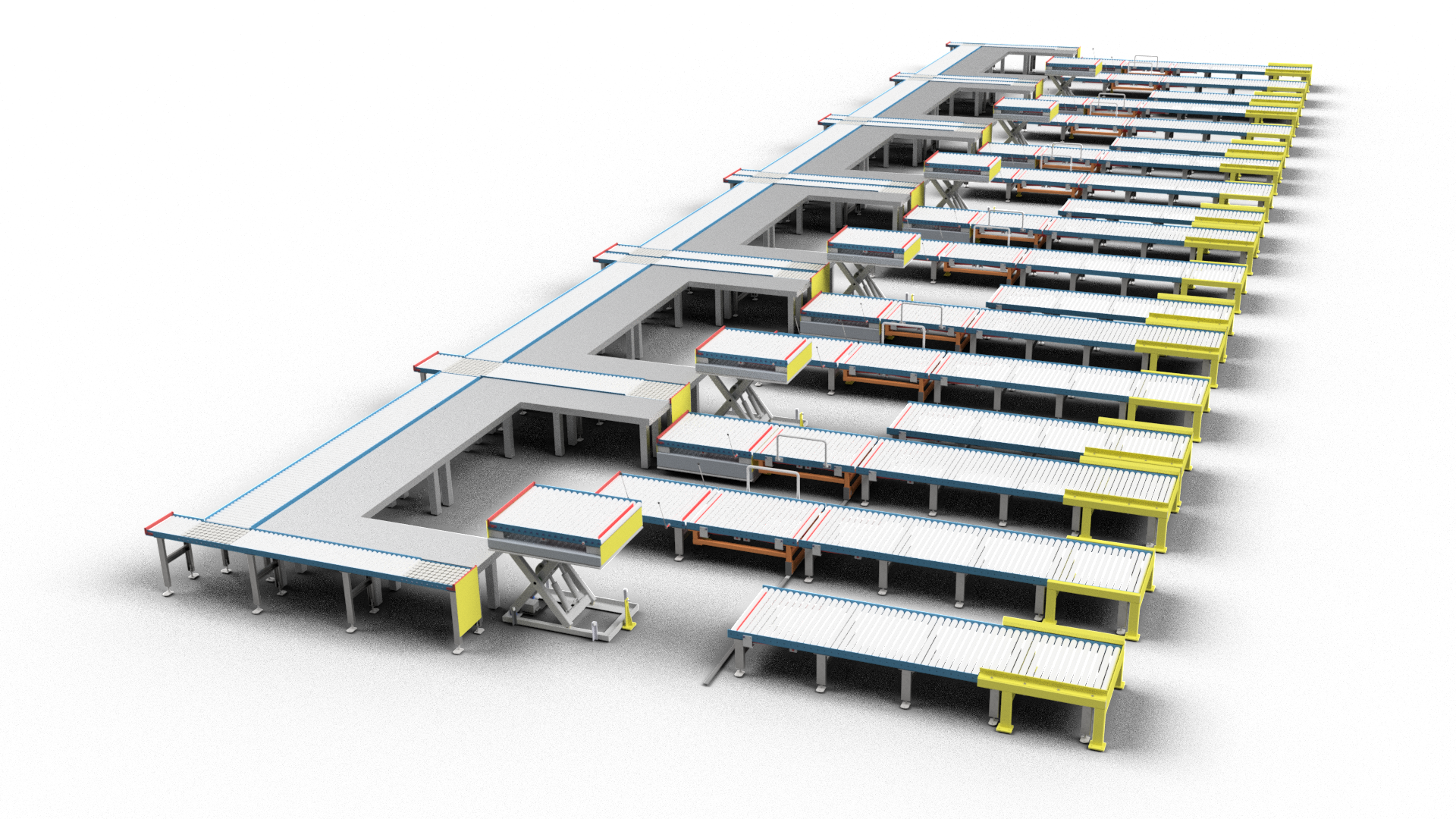
An almost completely non-driven conveyor line with trolleys and lifting units.
The basic concept has remained more or less the same, but safety has been significantly improved, for example with automatic stops, more robust guides and rams. The ergonomics have also been improved with clever details, including the addition of an auxiliary slope. Smaller details to protect the lever mechanism complete the picture. Today, low rolling resistance and smooth-running ball rollers facilitate the handling of the sometimes heavy cardboard boxes.
Facts and numbers
Conveyor elements
Idlers fitted
Ball casters installed
The customer benefit
The individually planned order picking lines are an ideal replacement for the old system. The conveyor line was installed and put into operation without any major disruption to day-to-day operations. Thanks to the high level of quality, a significantly longer service life can be expected, which also reduces maintenance costs and increases throughput! The most important advantages for our customer at a glance:
- Good price/performance ratio thanks to manual conveyor technology
- Increased ergonomics and occupational safety with little effort
- High operational reliability thanks to clever mechanical safety solutions
- Low maintenance requirements thanks to a robust design
- Durability thanks to high-quality components
Ergonomic assembly stations
The challenge
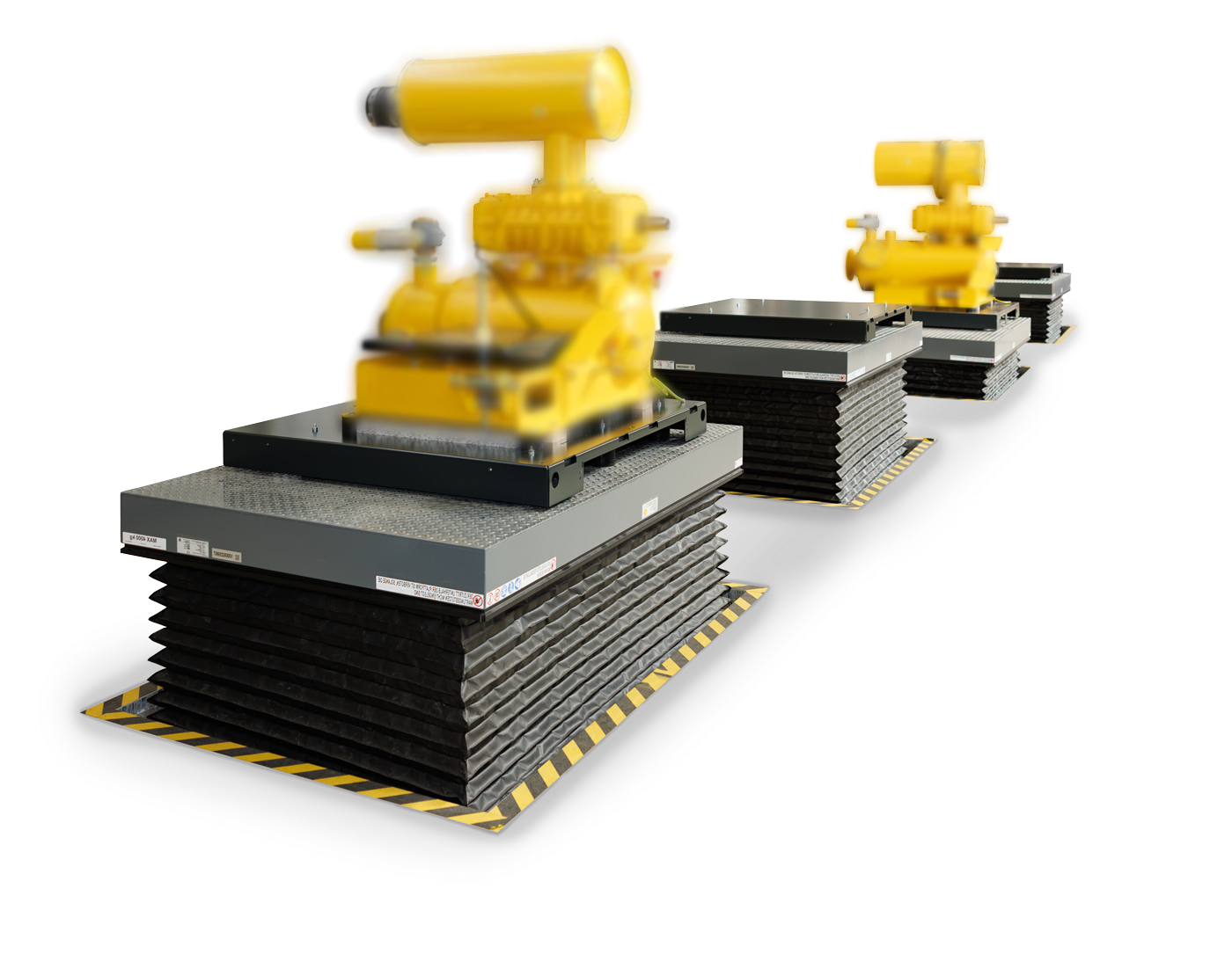
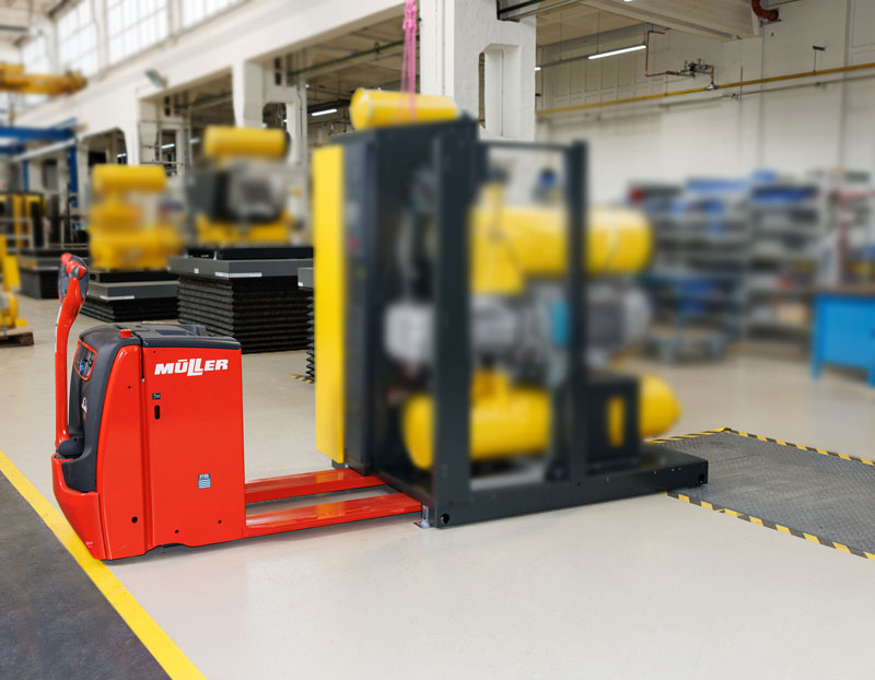
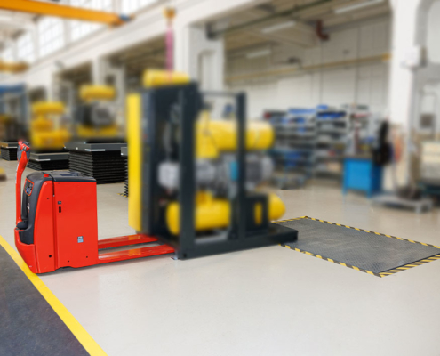
During the final assembly of blower systems, heavy compressed air generators have to be lifted to an ergonomic assembly height. The products weigh up to 4,100 kg and stand on assembly supports that are moved with a pallet truck or an ant. These are not suitable for safe and ergonomic final assembly.
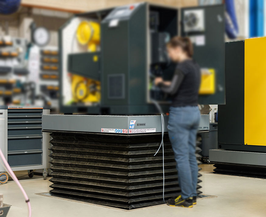
In addition to a ground-level task using a pallet truck, it is important that the safety technology is designed in such a way that the workers can work directly on the products and in such a way that there is no danger from the scissor lift tables or the lifted load. In addition, it should be possible to adopt a healthy posture during assembly so that physical strain is reduced and greater productivity can be achieved.
For efficient final assembly of the blowers, it is also important that the necessary tools and equipment are quickly available and that the safety technology optimally supports the work process. This is the only way to ensure that the end products meet the highest quality standards while at the same time guaranteeing the safety of the workers.
The solution
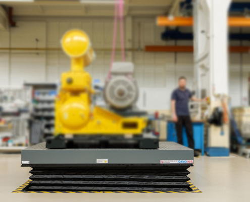
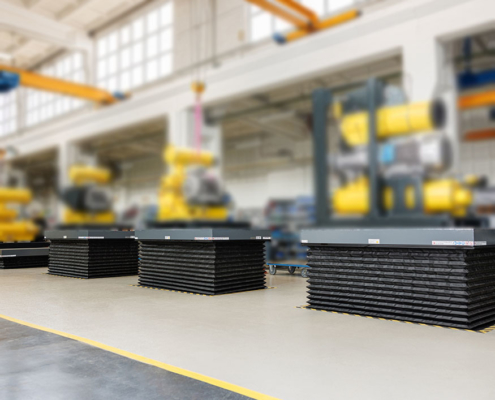
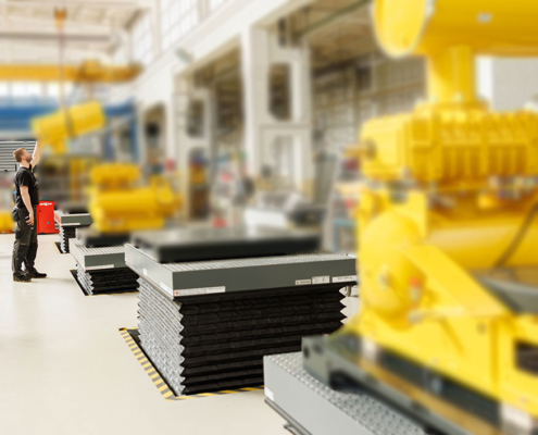
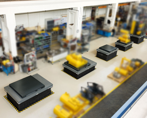
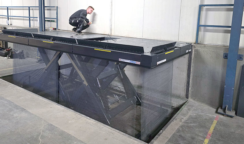
The assembly line was equipped with smaller blowers first, using three single scissor lift tables with a load capacity of 4,000 kg each. This was followed shortly afterwards by two further single scissor lift tables, each with a load capacity of 8,000 kg, for the assembly line with larger blowers.
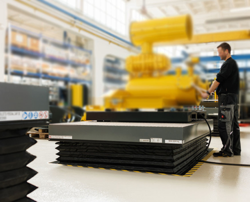
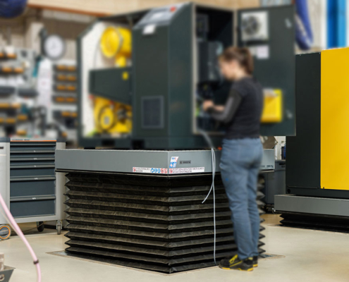
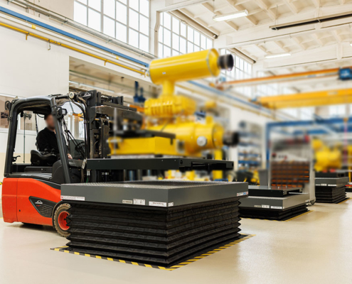
All lift tables were fitted with a bellows underneath the platform to prevent them from crawling underneath and to ensure good access protection. Another safety-relevant feature is the contact protection strips running underneath the platform, which prevent jamming during lowering.
The construction of the platform has been reinforced on the underside to ensure that it can be safely driven over with a pallet truck when lowered. Pilot valves on both cylinders ensure that the heavy load is lifted evenly and safely. Due to the high lifting cycles, additional replaceable stainless steel wear rails are installed under the rollers of the scissor packs. The lift tables installed in a pit can be easily serviced via a service flap even when lowered, so that the internal units are easy to reach.
Facts and numbers
Load capacity
Cycles per hour
Lifting time
The customer benefit
The individually planned single scissor lift tables are an ideal addition to the production lines. The hoists were installed and put into operation without any major disruption to day-to-day operations. Thanks to the high level of quality, a significantly longer service life can be expected, which also reduces maintenance costs and increases throughput! The most important advantages for our customer at a glance:
- Increased ergonomics and occupational safety with little effort
- High operational reliability thanks to clever mechanical safety solutions
- Low maintenance requirements thanks to a robust design
- Durability thanks to high-quality components
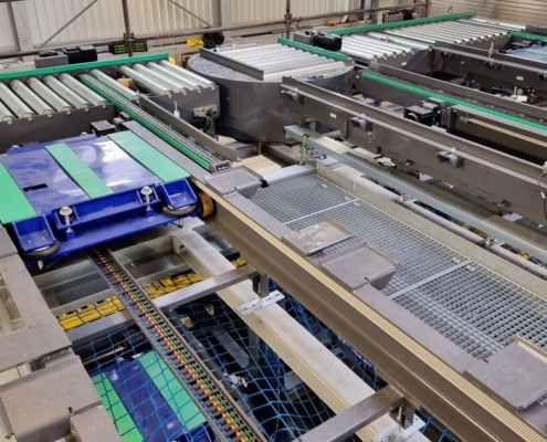
Safe handling of hazardous material drums
The challenge
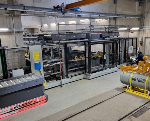
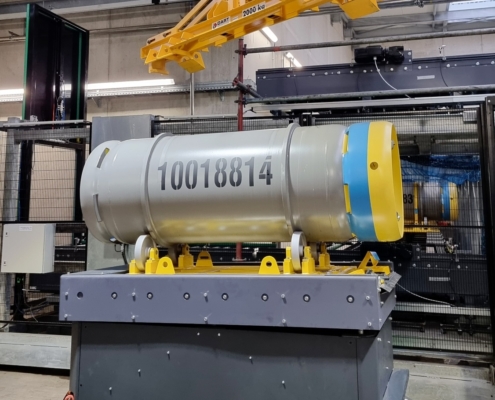
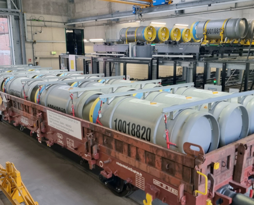
A hazardous substance drum receiving system with intermediate buffer is required for the new soot aftertreatment system to be set up at the Dortmund site.
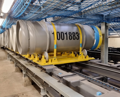
Specifically, the drums are delivered by rail on a wagon, which are to be removed within 24 hours by an overhead crane and stored in a buffer system.
The drums must be sorted and handled with extreme care in order to minimize the risk posed by the hazardous substance.
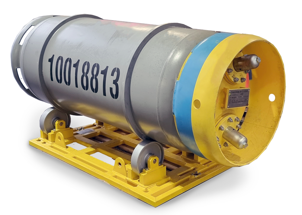
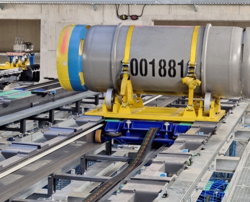
To ensure smooth transportation and safe unloading of the drums, the drums are loaded onto a drum carrier rack. On this rack, the drums go through the entire emptying process, which follows a strictly controlled procedure.
The solution
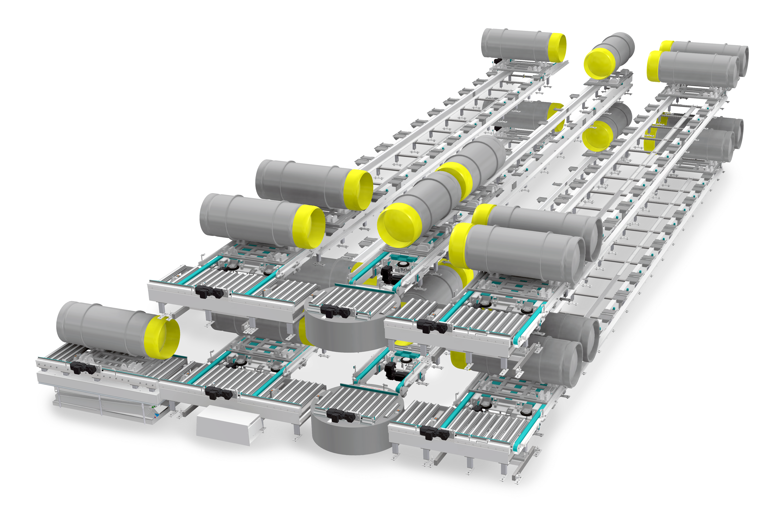
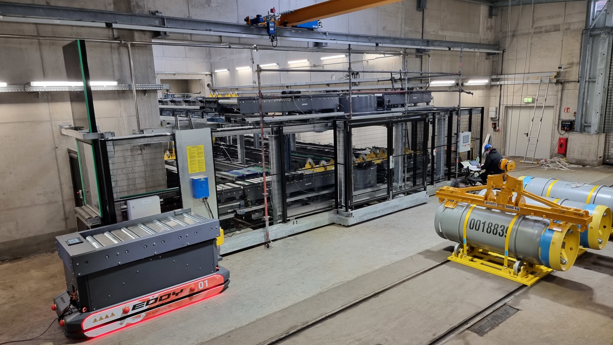
The wagon is loaded and unloaded via an overhead crane onto a barrel carrier frame, which is mounted on an automated guided vehicle (AGV). The AGV moves to the side of the wagon completely autonomously up to the loading station.
From there, it moves to one of the FiFo buffer sections, where the drums are stored and kept ready for further use.
For safe drum emptying, the conveyor system moves one drum at a time into the evaporation area on a lifting/tipping device and closes off the safety area with lifting gates.
After emptying, the drums are buffered on the upper conveyor line and stored until removal.
Are you interested in a conveyor system?
Then get in touch with us now
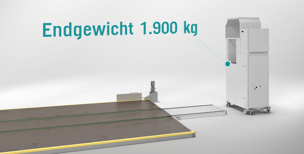
Successful lift table assembly with a system
The challenge
In the highly dynamic production environment of our valued customer, TRILUX GmbH & Co KG, we were faced with the challenging task of optimizing the efficiency and safety of material transport between two production halls with a height difference. The previous solution, a conventional lift table, was increasingly prone to failure and could no longer meet the increasing demands for flexibility, throughput and occupational safety. This limitation led to bottlenecks in production and posed a risk of downtime. An innovative, reliable and customized solution was urgently needed to ensure continuous operation and increase productivity.
The solution
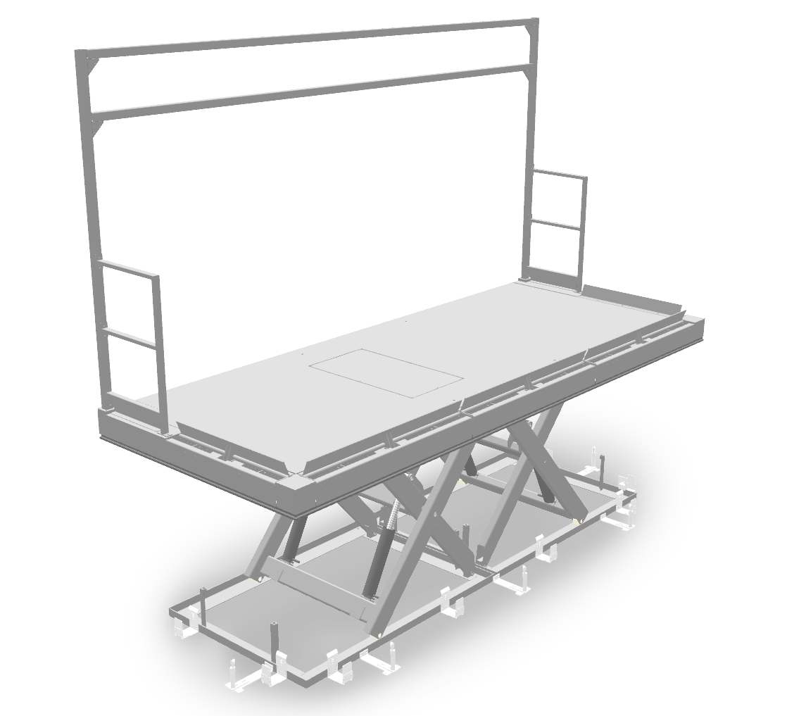
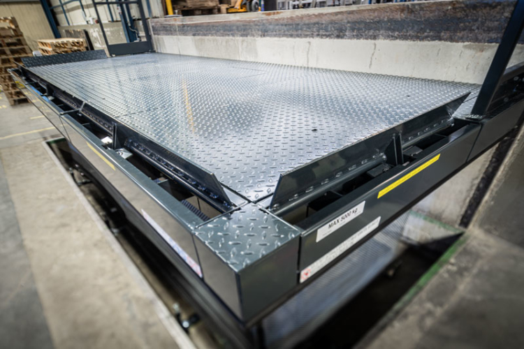
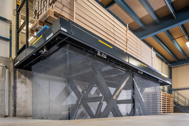
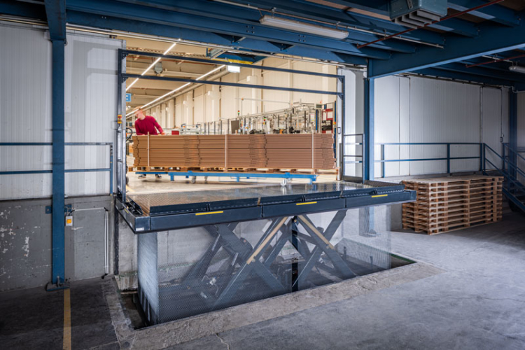
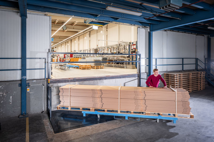
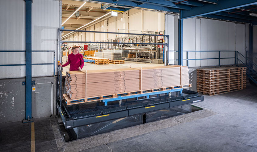
Our response to this challenge was the development and implementation of a state-of-the-art tandem scissor lift table. With platform dimensions of 5000 x 2000 mm and an effective lifting height of 1370 mm, it was specifically designed to seamlessly connect the two production levels and optimize the material flow. The key to success lay in the detailed adaptation to the specific needs of our customer.
Maximized occupational safety: Automatic roll-off protection on three sides and fall protection on the narrow sides, together with a safety portal for the upper level, minimize the risk of accidents at work and ensure safe operation.
Optimized operating flow: Seamless and efficient transportation between levels reduces waiting times and improves overall operational logistics, resulting in faster order processing.
Customization: By integrating reinforcement profiles underneath the platform and a job-specific safety chain curtain, the lift table ensures exceptional stability and safety, even under the most demanding load conditions.
Increased throughput capacity: The size and load-bearing capacity of the lift table enable the transportation of industrial trucks together with the transport containers for lamps, which leads to a significant increase in productivity.
How to successfully assemble a lift table
The tailor-made solution for our customer underlines our focus on specific requirements and our commitment to improving production processes and the working environment through innovative lifting technology. Professional assembly is the cornerstone of such a solution to guarantee fast and safe commissioning. Thus, the use of this tandem scissor lift table can not only overcome technical challenges, but also create significant added value for the customer by increasing safety, efficiency and productivity.
1. Preparations at the installation site
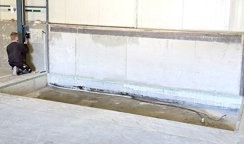
The floor or the pit (Download: pit layout) must have a smooth and level surface for the installation of the lift table, it is recommended that edge protection is fitted and heavy-duty anchors are used. Empty conduits are used for the supply and control lines and drainage provided by the customer to prevent moisture. The position of the unit should be defined for this purpose. On-site supply lines require sufficient length, a lockable main switch and appropriate fuses. Please ensure that fall and access protection is provided!
2. Delivery and unloading
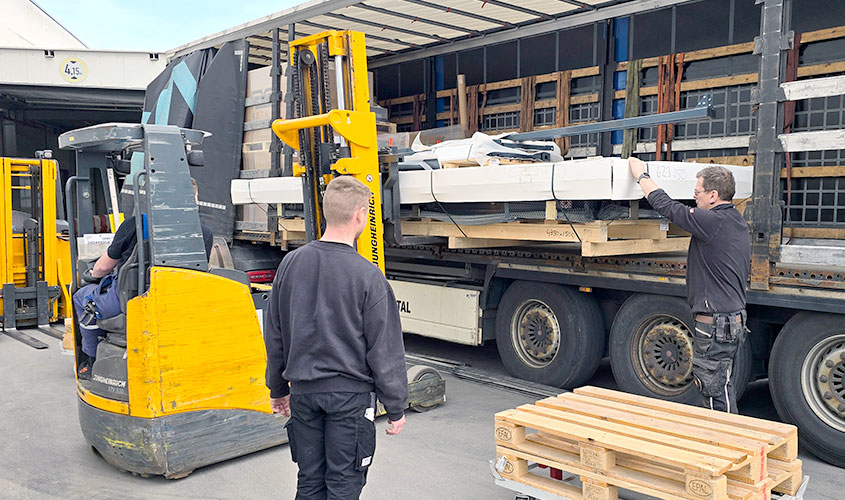
At the time of delivery, the unloading location should be freely accessible and a suitable lifting aid with operator should be available. Instructions for proper unloading must be taken from the documentation in advance. In particular, suitable lifting and securing equipment must be used. Before unloading and acknowledging the accompanying documents, the goods must be checked to ensure that they are intact and a note must be made if necessary.
3. In-house transportation to the installation site
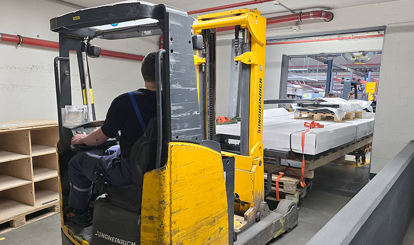
The transport route to the installation site should be defined before unloading. The corridor route must be checked for sufficient height, width and maneuvering space. Under certain circumstances, keys should be kept ready for doors and gates. During transportation, care must be taken to ensure that the load is correctly secured by qualified personnel. If the transport is obstructed by the company, this must be announced accordingly in order to keep operational disruptions to a minimum.
4. It all depends on professional installation
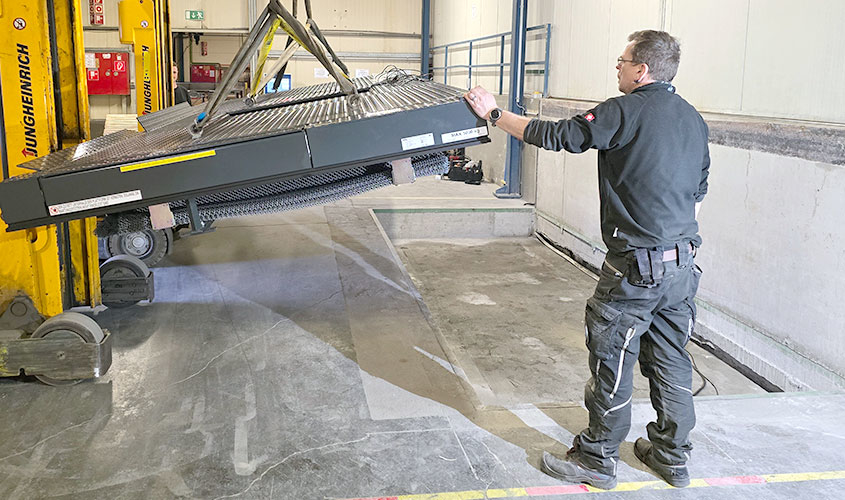
In accordance with the documentation, the lift table must only be lifted using eyebolts at the lifting points provided; lifting straps under the platform can damage safety equipment and the cylinders. Supply lines, hydraulic hoses and the contact protection strip must also be protected from damage before lifting and lowering into the pit. Furthermore, care must be taken to ensure correct alignment and level positioning. Depending on the ground conditions, heavy-duty or adhesive anchors can be used for fastening.
5. Commissioning and safety check
After mechanical installation, the electrical connection must be carried out by suitably qualified personnel. Beforehand, the installation site should be cordoned off and secured with appropriate signage (“trial operation”). The safety measures should only be removed after an electrical and mechanical function and safety check, as well as all on-site safeguards (railings etc.). Approval is given during final acceptance.
6. Final acceptance and maintenance
Handover takes place with an installation and final acceptance report, as well as instruction of the operating personnel, who must be present at the end of the installation work. The lift table is then released for operation and ready for use. If an inspection is required in accordance with the German Ordinance on Industrial Safety and Health, we will be happy to accompany this for you. In addition, the system should be inspected and serviced annually.
Are you interested in a lift table?
Then get in touch with us now
Lindner NORIT GmbH: Efficient coating, testing and palletizing on a piecework basis
We swap old for new, with no downtime!
The aim was to replace the system as smoothly as possible during the company vacations and to commission the system in parallel with the start of production in the new year. Customer experience from the production of the old system was incorporated into the new solution. The new system should not only palletize and transport different panel thicknesses, but also offer the possibility of testing and post-treatment. The new conveyor solution was supplemented by a spraying system, a measuring system for thickness measurement, two scales, a paternoster and a printer. In addition, the entire system was to be integrated into the existing production management system (PMS).
After the sanding line is before quality control
As with the old system, we take the gypsum fiberboards directly from a sanding system. In the first step, the boards, which are processed in pairs, are separated and fed to the thickness measurement system. The boards are measured at full conveyor speed and, if they deviate from the tolerance, are ejected to the inspection station for checking.
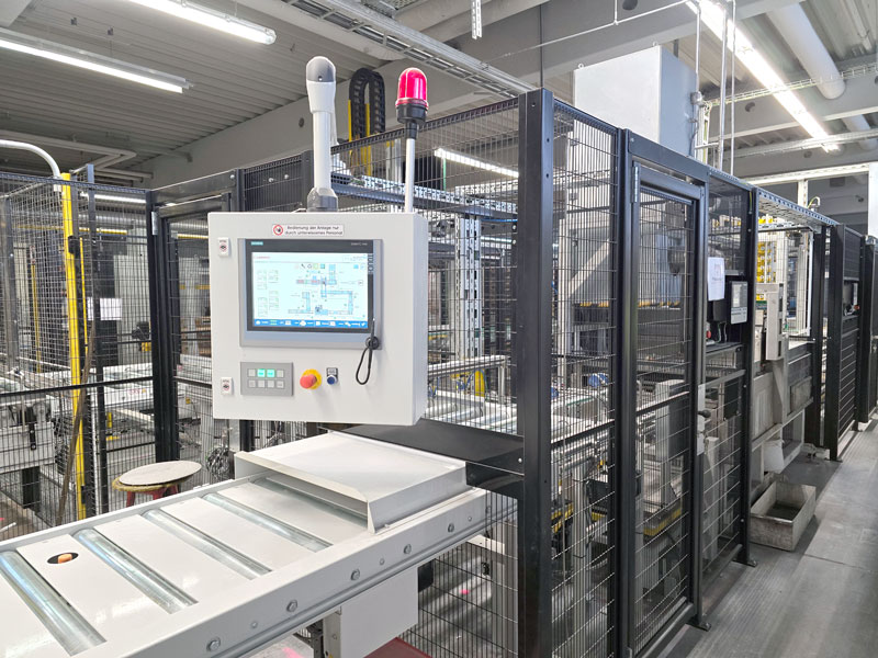
The operator controls the entire system via the control panel and is able to eject individual gypsum fiber boards for further inspection. Up to four boards can be inspected and processed simultaneously on the partially driven roller conveyor without interrupting the entire system.
The boards are then fed back into the system fully automatically on request and conveyed to the first scale. Here, random samples are weighed before and after the spraying system for quality assurance. The results are in turn forwarded to the PMS and can be monitored from there. To avoid a backlog during weighing, the panels are lifted off the belt conveyors by eccentric lifters so that subsequent panels can continue to be conveyed without interruption. This also prevents product jams.
A paternoster for drying after the spraying system
The moist gypsum fiberboards from the spraying system must first be dried on a pallet before palletizing. A space-saving buffer solution is required to ensure a high throughput and good ventilation of the boards at the same time.
Our paternoster system, individually adapted to this application, has a capacity of 22 boards and is the ideal solution here. Using servo drive technology, the boards are first conveyed upwards on a few support points, transferred there and conveyed downwards again in a cycle. During this time, the gypsum fiberboards can be optimally ventilated and dried.
If, in special cases, no drying and buffering of the boards is required, the paternoster can be deactivated. In this case, the product is conveyed underneath via a belt conveyor.
The individual panels are then transported individually on a roller conveyor system to the stacking portal, where they are accumulated in pairs and centered.
Precise palletizing in piecework
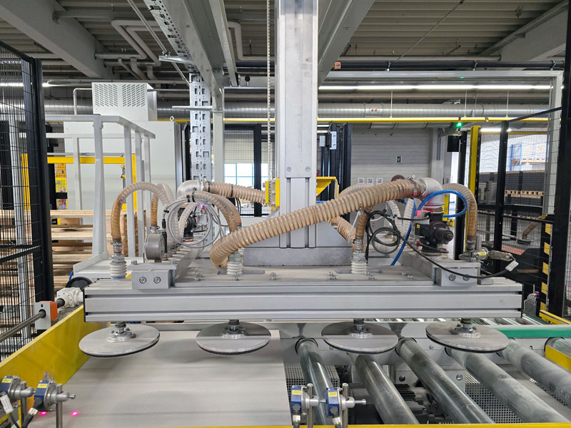
Our palletizing gantry system was used here as the basis for the stacking gantry. The standard version with pneumatic grippers was replaced by 8 vacuum suction cups to transport the panels safely and without damage from the pick-up to the stacking station. Precise vertical and horizontal positioning is achieved by servo-drive controlled belts.
The pairs of panels on a wooden pallet must be palletized in a perfect layer pattern in the high cycle of the overall system.
For this purpose, vacuum suction cups lift the two gypsum fiber boards and the arm of the gantry system moves them horizontally to the pallet conveyor system, where the boards are stacked on an empty pallet. This stacking process is repeated up to an adjustable number of layers and the stack is printed with a batch number using a printer for tracking purposes.
Once the final number of layers has been reached, the full pallets are conveyed to the removal area, where they are removed using a forklift truck.
Pallet feeder and batch printer
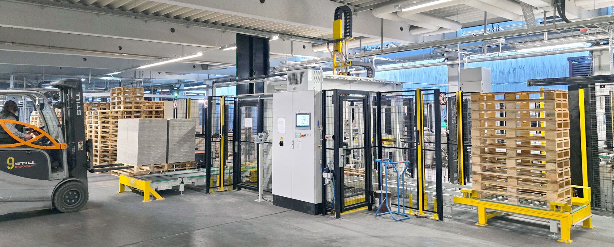
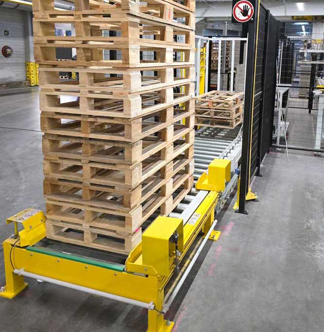
The pallets are loaded by forklift truck. The pallets are picked up by the system and fed to the pallet magazine via roller conveyors, where they are separated. To ensure that the filled pallet can be replaced smoothly with an empty one, the separated pallet is moved to a waiting position directly in front of the stacking station.
Once the pallet has been loaded with sufficient panels, the batch number is printed on the side.
Once the preset number of layers has been reached, the pallet is exchanged without affecting the cycle time of the stacking gantry. This ensures continuous palletizing without waiting times and product jams.
The finished pallet with a perfect stacking pattern is now transported out of the safety area by a corner transfer unit through a safety light grid with a muting system. An indicator light signals the logistics department to remove the pallet and send it to its next destination.
Facts and figures
Plates per day
Pallets per hour
Pallets per year
Communication of all components
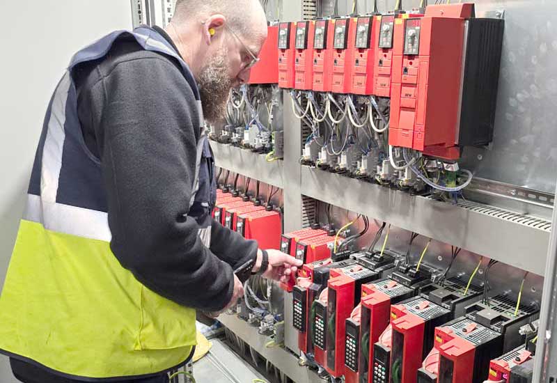
For full control of all control components such as touch panels, frequency converters and decentralized peripherals, ALFOTEC also relies on future-proof communication via Profinet in this system.
An interface to the customer’s Oxaion system was created for full integration into the LINDNER Production Management System. This enables order management and monitoring of system availability from the higher-level control system. The system is used to manage orders, record and monitor quantities and system status.
The system is divided into 10 functional areas and 4 safety areas to reduce downtimes in the event of maintenance and to ensure a quick restart. These can be switched off separately. The safety areas can be accessed via a total of 10 safety doors.
The customer benefit
The individually planned conveyor system is an optimal replacement for the old system. The conveyor line was installed and put into operation without any major disruption to day-to-day business. Due to the significant increase in throughput, further production capacities and thus additional capacity reserves are to be created in the future. The most important advantages at a glance:
- Significant increase in throughput
- Significantly increased degree of automation
- Improving ergonomics and occupational safety
- Reproducible quality in the production of panels
- Quality assurance through thickness measurement and weighing
- Optimum system availability thanks to functional and safety areas











![20200624_120802-scaled[1]](https://qs.alfotec.com/wp-content/uploads/20200624_120802-scaled1.jpg)
![20200624_121420-scaled[1]](https://qs.alfotec.com/wp-content/uploads/20200624_121420-scaled1.jpg)
![rollenbahn_anschlag_mechanisch_detail[1]](https://qs.alfotec.com/wp-content/uploads/rollenbahn_anschlag_mechanisch_detail1-495x400.jpg)
![aufgabestation_zentrierhilfen[1]](https://qs.alfotec.com/wp-content/uploads/aufgabestation_zentrierhilfen1-495x400.jpg)
![rollenbahn_fahrwagen_anschlag_mechanisch[1]](https://qs.alfotec.com/wp-content/uploads/rollenbahn_fahrwagen_anschlag_mechanisch1-495x400.jpg)
![20200624_121420-scaled[1]](https://qs.alfotec.com/wp-content/uploads/20200624_121420-scaled1-495x400.jpg)
